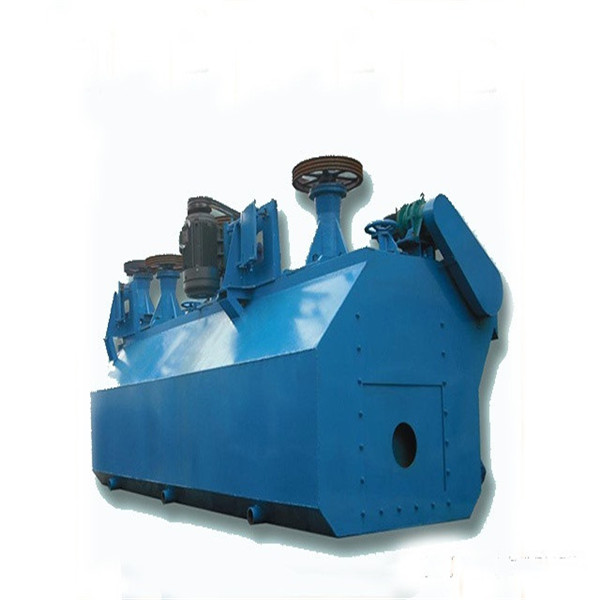
The inflatable stirring flotation machine is not only equipped with a mechanical stirring device, but also forced to blow air by using an external fan, but the mechanical stirring device generally only plays the role of stirring the pulp and distributing the air flow. Aeration and stirring are separate.

Features:
1. The aeration volume can be increased or decreased according to the needs and is easy to adjust and keep constant, so it is beneficial to improve the processing capacity and selection index of the flotation machine;
2. The impeller does not have a suction effect, so the speed is low, the power consumption is low, the wear is small, and the brittle minerals are not easy to produce sludge phenomenon;
3. Due to the large processing capacity and shallow grooves, the power consumption per unit of processing capacity is low. The disadvantage is that it needs to add a set of air pressure system, and the sand pump should be used to lift the intermediate product when it returns. Such flotation machines include CHF-X type, XJC type, BS-C type, KYF type, BS-K type, LCH-X type, CLF type, etc.
working principle
When the inflatable stirring flotation machine is working, it relies on the motor transmission device and the hollow main shaft to drive the impeller to rotate. The pulp in the tank is sucked into the lower blade of the impeller through the inner edge of the lower blade of the impeller from all sides through the bottom of the tank. At the same time, the low-pressure air fed from the outside enters the air distribution in the lower impeller cavity through the beam, the air regulating valve and the hollow main shaft. Then it enters between the lower blades of the impeller through the small holes around the air distributor. After the pulp and air are fully mixed between the lower blades of the impeller, they are discharged from the outer edge of the lower blade of the impeller.
Due to the combined action of the rotation of the impeller of the flotation machine and the cover plate and the center cylinder, a certain negative pressure is generated in the upper blades of the impeller, so that the medium ore foam and the ore feeding flow into the center barrel through the middle ore pipe and the ore feeding pipe, and enter the Between the upper blades of the impeller, it is finally discharged from the outer edge of the upper blade. The slurry and air mixture discharged from the outer edge of the lower blade of the impeller and the medium and feed ore discharged from the outer edge of the upper blade of the impeller enter the main pulp in the tank after the stator installed around the impeller is stabilized and oriented, and the mineralized bubbles rise to A foam layer is formed on the surface of the pulp, part of the pulp is returned to the lower blades of the impeller for recirculation, and the other part enters the next tank through the circulation holes on the wall between the tanks for re-selection or discharge as a final product.
|
Type |
Slot volume (M3) |
Impeller diameter (mm) |
Production capacity (m3/min) |
Impeller speed (R/min) |
Scraper speed (R/min) |
Impeller motor power |
Scraper motor power |
Dimensions (mm) |
Equipment ton/slot |
|
HT13 |
0.13 |
200 |
0.05-0.16 |
600 |
17.5 |
1.5 |
0.55 |
2100*1865*900 |
0.35 |
|
HT23 |
0.23 |
250 |
0.12-0.28 |
500 |
17.5 |
1.5 |
0.55 |
2625×1130x1290 |
0.41 |
|
HT35 |
0.35 |
300 |
0.15-0.5 |
470 |
17.5 |
2.2 |
0.55 |
3012×1350×1327 |
0.45 |
|
HT62 |
0.62 |
350 |
0.3-0.9 |
400 |
16 |
3 |
1.1 |
3798×1464×1530 |
0.85 |
|
HT110 |
1.1 |
500 |
0.6-1.6 |
330 |
26 |
5.5 |
1.1 |
4679x1820x1942 |
1.24 |
|
HT280 |
2.8 |
600 |
1.5-3.5 |
280 |
26 |
11 |
1.1 |
7750x1600x1100 |
2.43 |
can not be empty
The E-mail format is not correct
can not be empty
